Bose SoundTouch rescue
I build a quick and dirty internet radio streaming box with arcade-style buttons to not throw away the Bose SoundTouch system.

Hey 👋
Another day when the cloud business model did not work. Bose shuts down their cloud services for SoundTouch models.


Who knew that a forever-running service would cost money and resources, like, forever?

I think the people who allowed such a design should be fired. The internet radio part could be implemented on the damn device. I really do not get it.
In the linked LINUX Unplugged episode, they are also talking about how this is a very insecure device. Telnet is open, and you can get root on this when you place a specific text file on a USB stick. Good for the consumer in the end.
 Jupiter Broadcasting
Anyway. We had one of those devices for my grandma since she only listens to very niche internet radio streams, and that did stop a couple of weeks ago. 😮💨
Enough complaining, more problem-solving.
I heard there were some people working on hacked firmware, new apps, and all this stuff. But I needed a way simpler solution for my grandma. I wanted to add big buttons, like these arcade ones she can press. No app, no web interface, no nothing.
Also, this project should be done fast. 🐌
I had a Raspberry Pi 3 in my drawer and started to look for software that had GPIO support and could use the SoundTouch just as an AUX device.
I found: Phoniebox
 Micz Flor
I decided to go with the latest future3 branch.
 MiczFlor
Software Stack
This was the easy part. Run the installer and then follow a few steps to add the radio streams and GPIO config.
Each station has to be its own folder with the file called livestream.txt.
cat WDR2-Ostwestfalen-Lippe/livestream.txt
http://wdr-wdr2-ostwestfalenlippe.icecast.wdr.de/wdr/wdr2/ostwestfalenlippe/mp3/128/stream.mp3
I added like 6 or so.
You cannot add multiple streams to one folder.
For GPIO, you have to enable it here:
gpioz:
  enable: true
  config_file: ../../shared/settings/gpio.yaml
GPIO config is pretty easy as well, just a few YAML blocks and you are done:
cat gpio.yaml
# Provides a few selected examples of GPIO configuration
# Check out the documentation for many more configuration recipes
# documentation/builders/gpio.md
pin_factory:
  type: rpigpio.RPiGPIOFactory

input_devices:

  Radio1:
    type: Button
    kwargs:
      pin: 27
    actions:
      on_press:
        alias: play_card
        args: [WDR2-Ostwestfalen-Lippe]
        kwargs:
          recursive: true

  Radio2:
    type: Button
    kwargs:
      pin: 17
    actions:
      on_press:
        alias: play_card
        args: [SW-Plautdietsch]
        kwargs:
          recursive: true
  Radio3:
    type: Button
    kwargs:
      pin: 4
    actions:
      on_press:
        alias: play_card
        args: [SW-Russisch]
        kwargs:
          recursive: true
  Radio4:
    type: Button
    kwargs:
      pin: 3
    actions:
      on_press:
        alias: play_card
        args: [SW-Live]
        kwargs:
          recursive: true

  Radio5:
    type: Button
    kwargs:
      pin: 2
    actions:
      on_press:
        alias: play_card
        args: [SW-Deutsch]
        kwargs:
          recursive: true

  Back:
    type: Button
    kwargs:
      pin: 24
    actions:
      on_press:
        alias: next_song

  TogglePlayback:
    type: Button
    kwargs:
      pin: 23
    actions:
      on_press:
        alias: toggle

  Next:
    type: Button
    kwargs:
      pin: 18
    actions:
      on_press:
        alias: next_song


  IncreaseVolume:
    type: Button
    kwargs:
      pin: 14
      hold_time: 0.75
      hold_repeat: True
    actions:
      on_press:
        alias: change_volume
        args: +5

  DecreaseVolume:
    type: Button
    kwargs:
      pin: 15
      hold_time: 0.75
      hold_repeat: True
    actions:
      on_press:
        alias: change_volume
        args: -5
The complex part was the wiring and remembering which cable goes where. So I took some notes for my future self, to not hate me if I have to debug it.
This is for me, not for you. 😉 As I have almost cryptographically safe handwriting. It is like written once and read once.
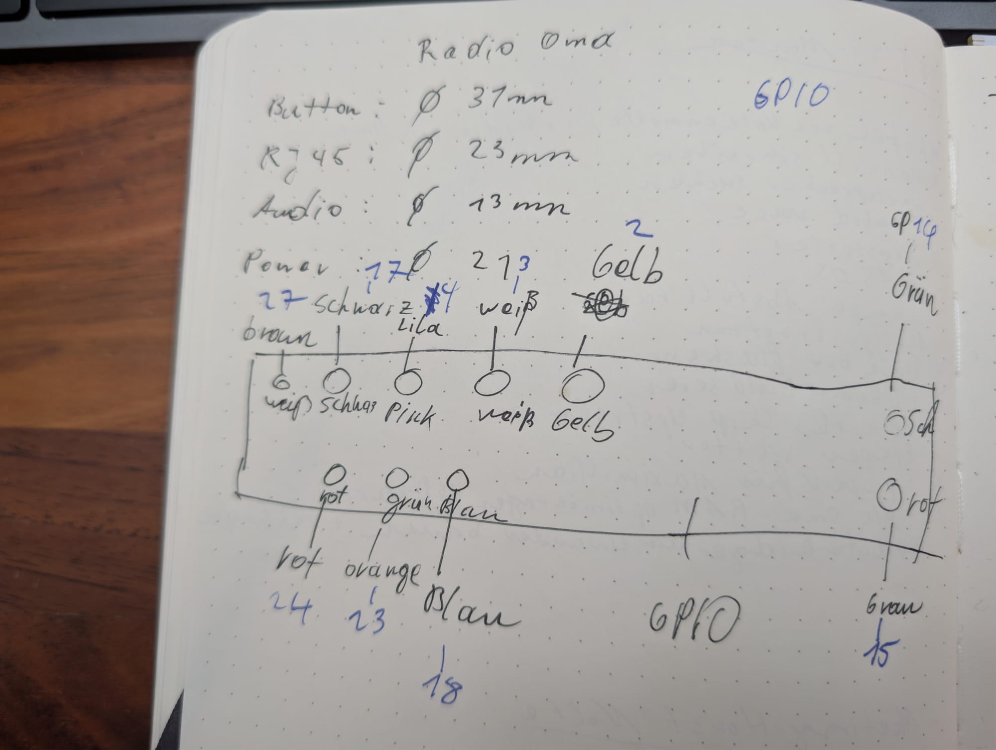
I just noted down where my buttons are, the color of that button, the color of the GPIO cable, and the PIN it will go to on the Raspberry Pi.
In hindsight, a table would be better, but hey 🤷
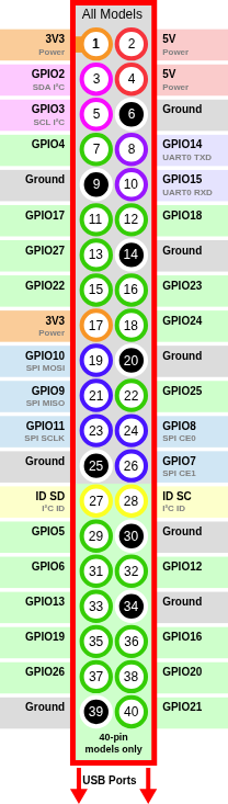
The pinout I used for the GPIO pins.
Last thing: I wanted to make the SD card read-only. First, I was thinking of implementing a few things the Armbian project did to make SD cards last longer. But eventually I found the read-only overlay file system in the raspi-config menu.
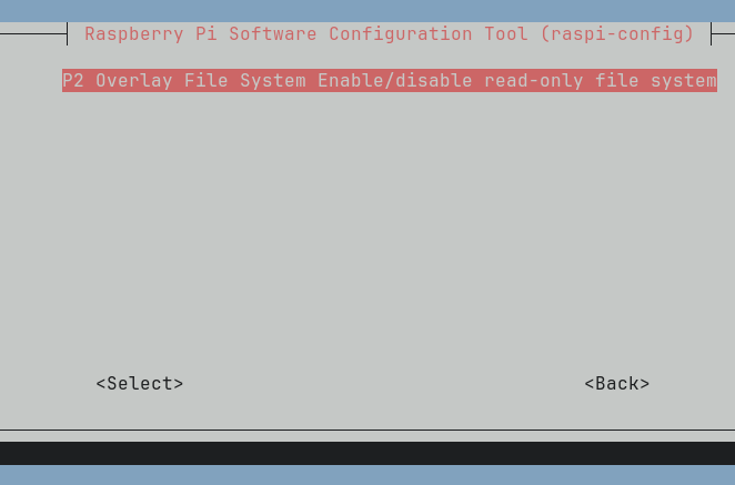
That is perfect! Just enable it, reboot, and no writes are done. This will prevent the SD card from dying when power is unplugged. Perfect use case!
andrej@omamusik:~$ mount | grep mmcblk
/dev/mmcblk0p2 on /media/root-ro type ext4 (ro,relatime)
/dev/mmcblk0p1 on /boot/firmware type vfat (ro,relatime,fmask=0022,dmask=0022,codepage=437,iocharset=ascii,shortname=mixed,errors=remount-ro)
I added Tailscale to that box as well. When I need to connect, which I do not intend, it is there.
Hardware
The Raspberry Pi 3 was in a drawer. I still had the box from my LTT water bottle, which looked decent. So that was my case.
I had a bunch of wire and solder stuff at home anyway.
I ordered:
- 10 arcade buttons
- Micro USB extension
- TRS extension with plate
- RJ45 Rack
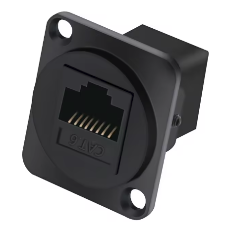
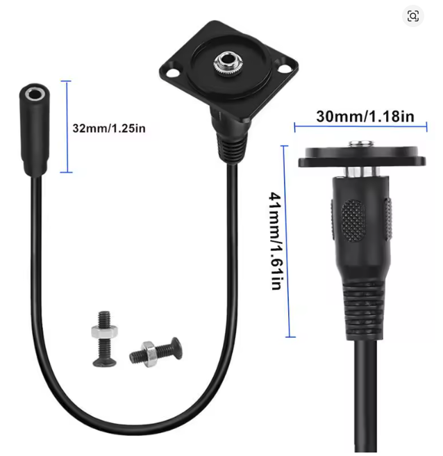
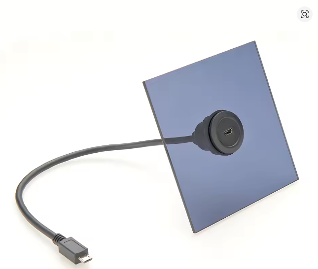
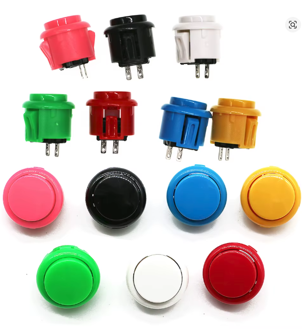
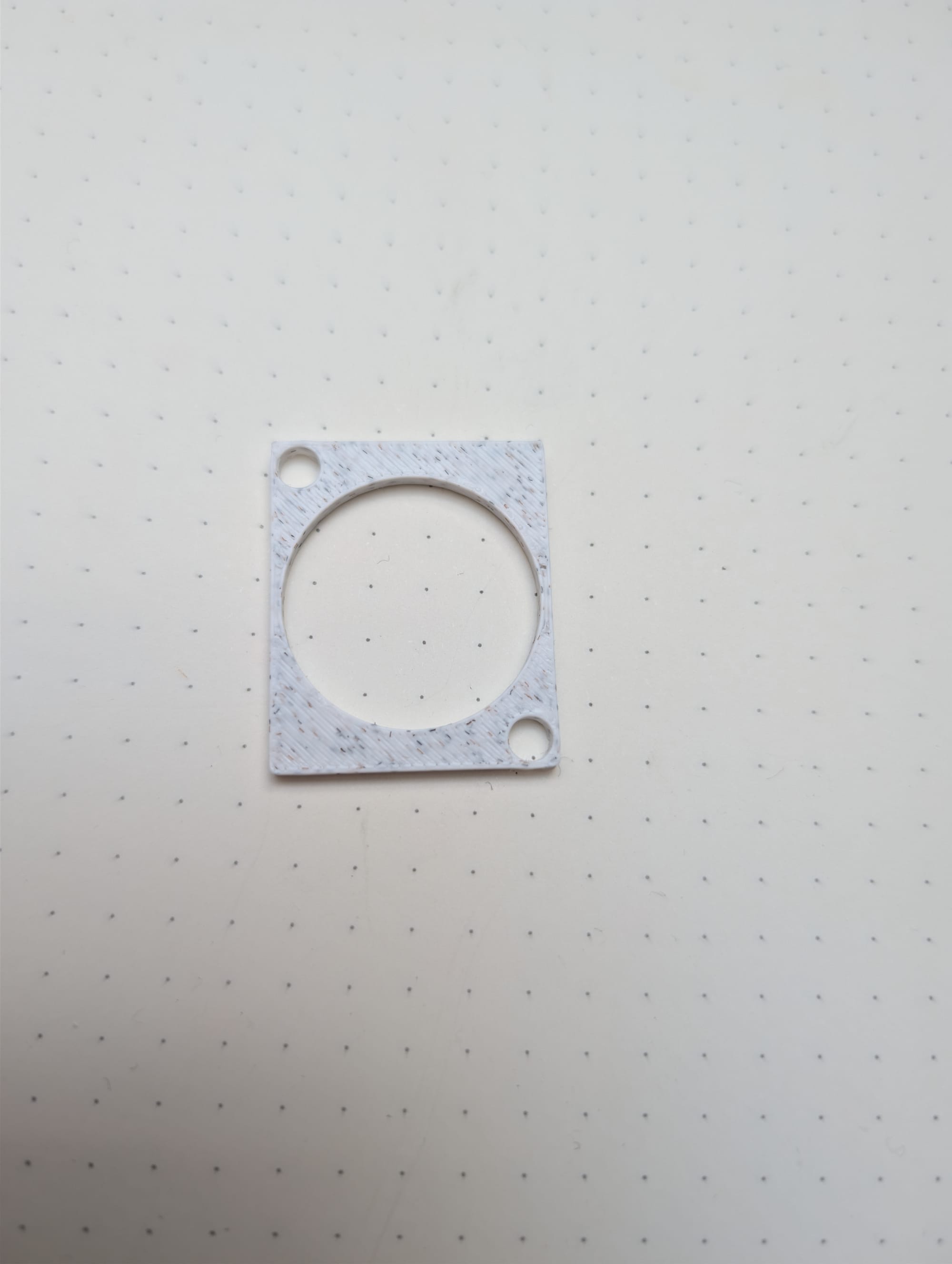
I quickly designed a plate to hold the screws/nuts on the rear side of the extensions with FreeCAD.
And after lots of stripping cables, soldering, etc., the result looked like this:
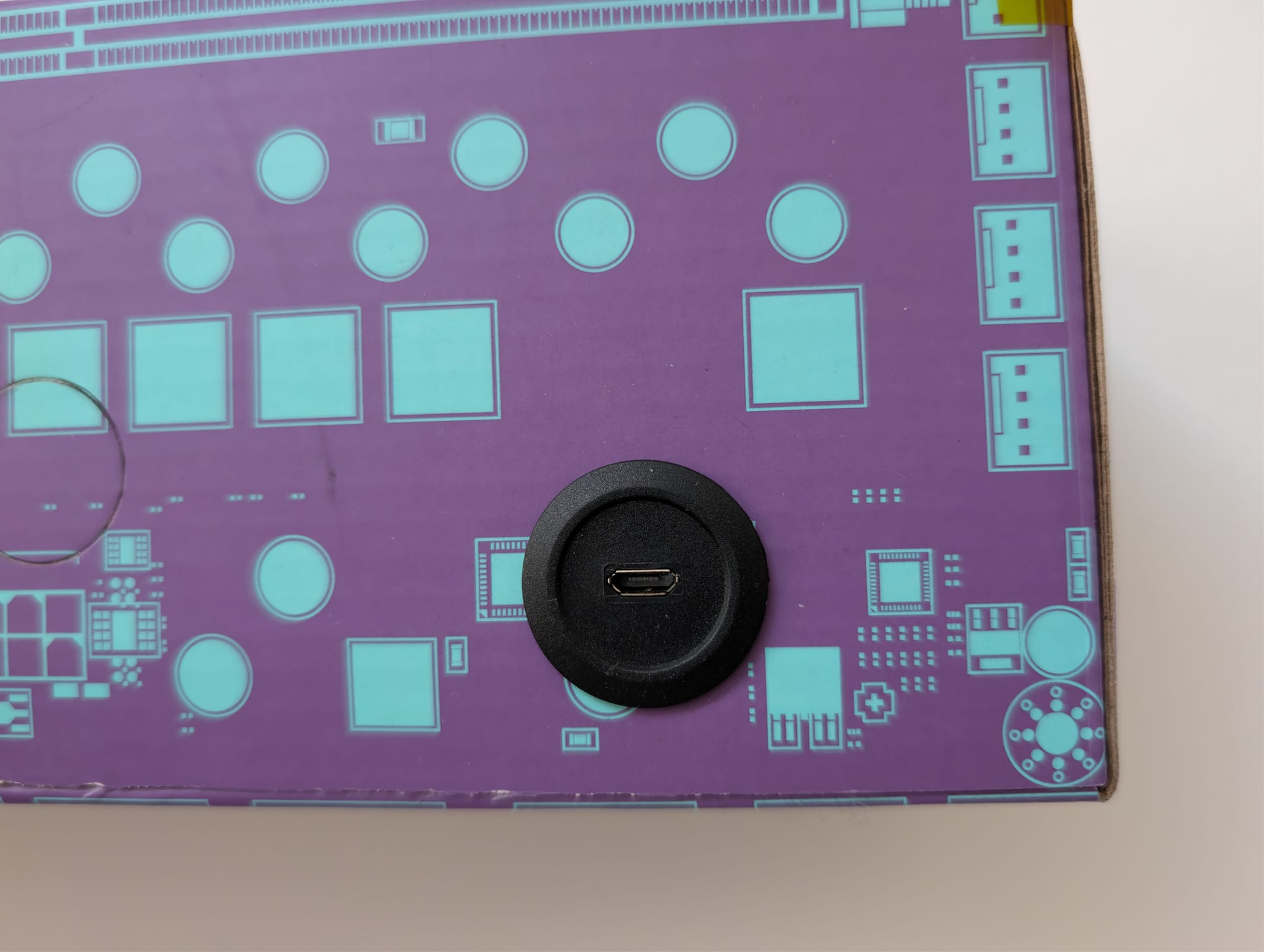
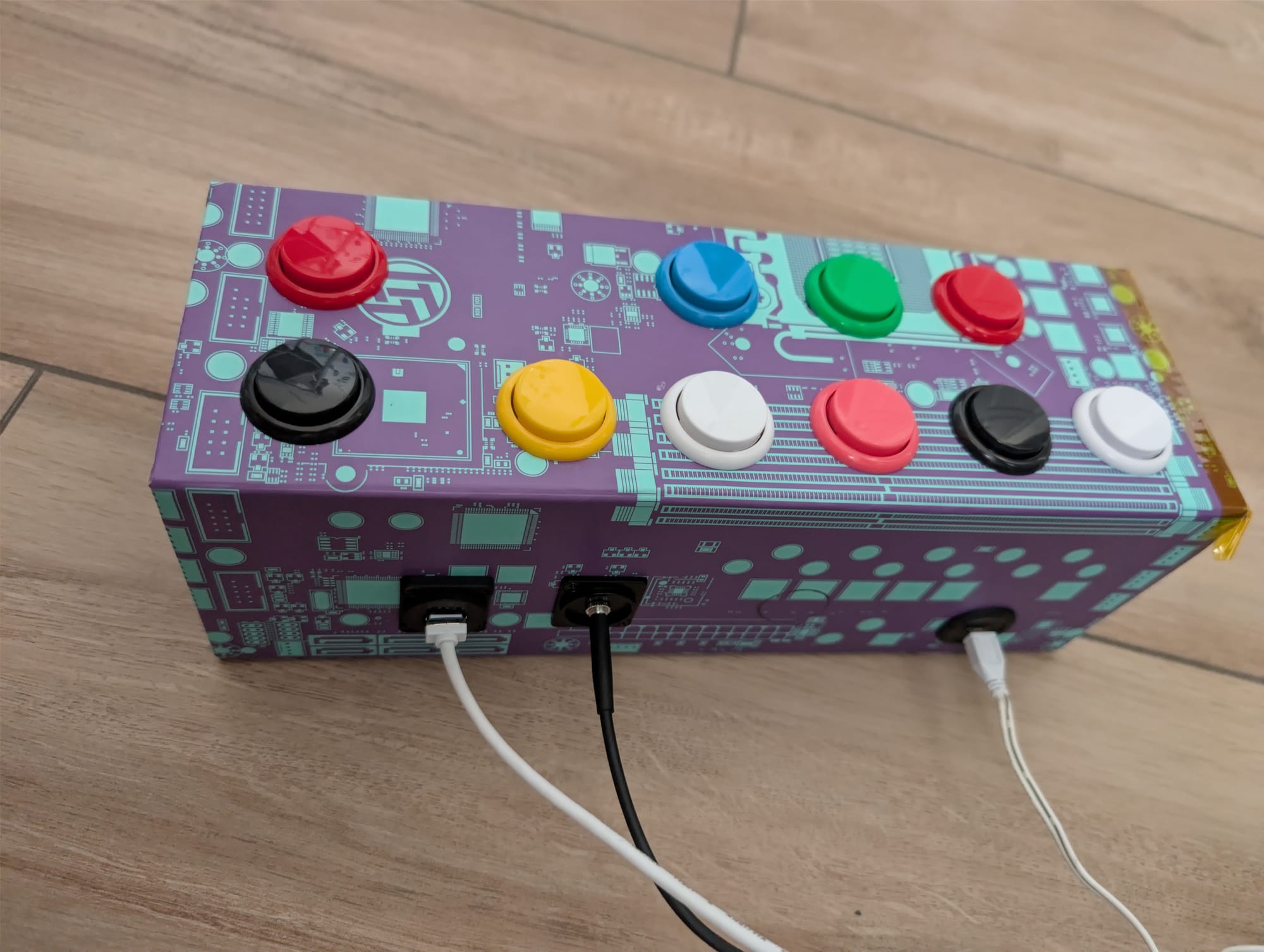
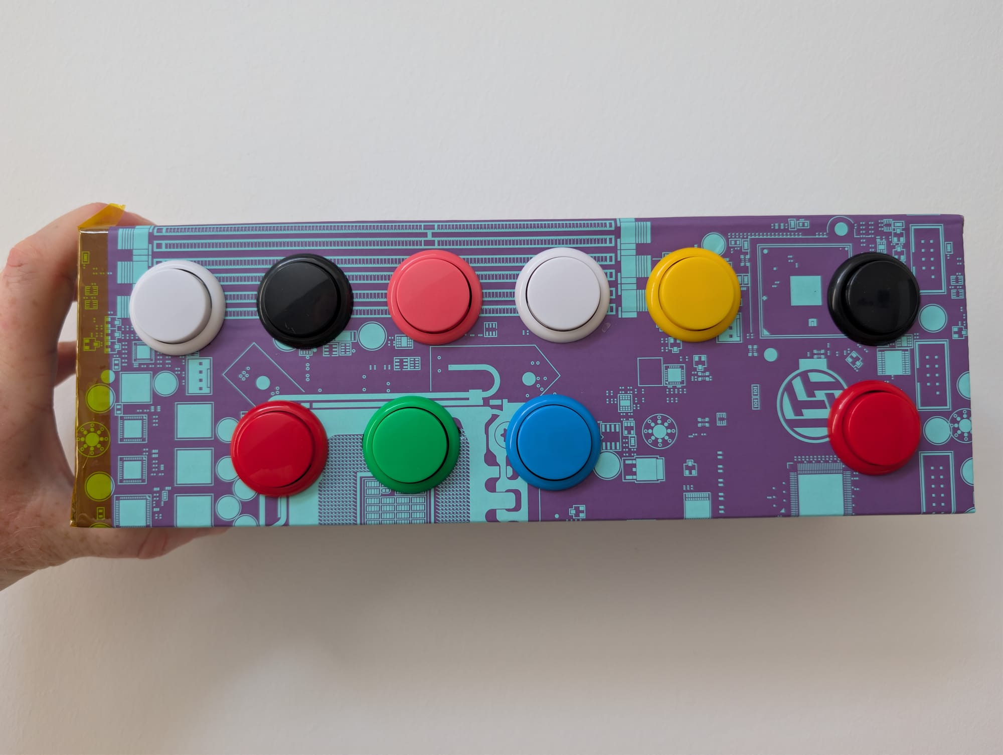
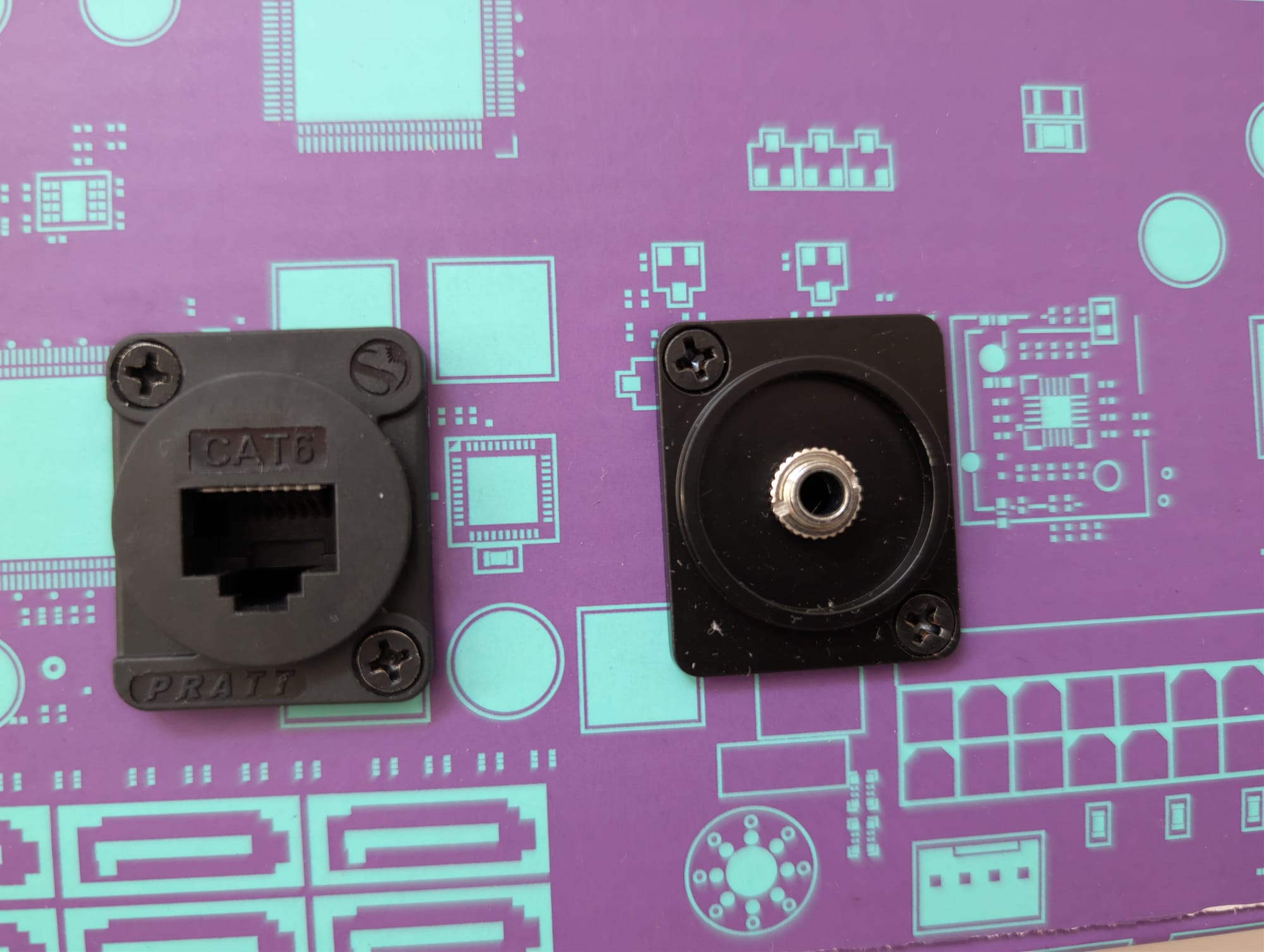
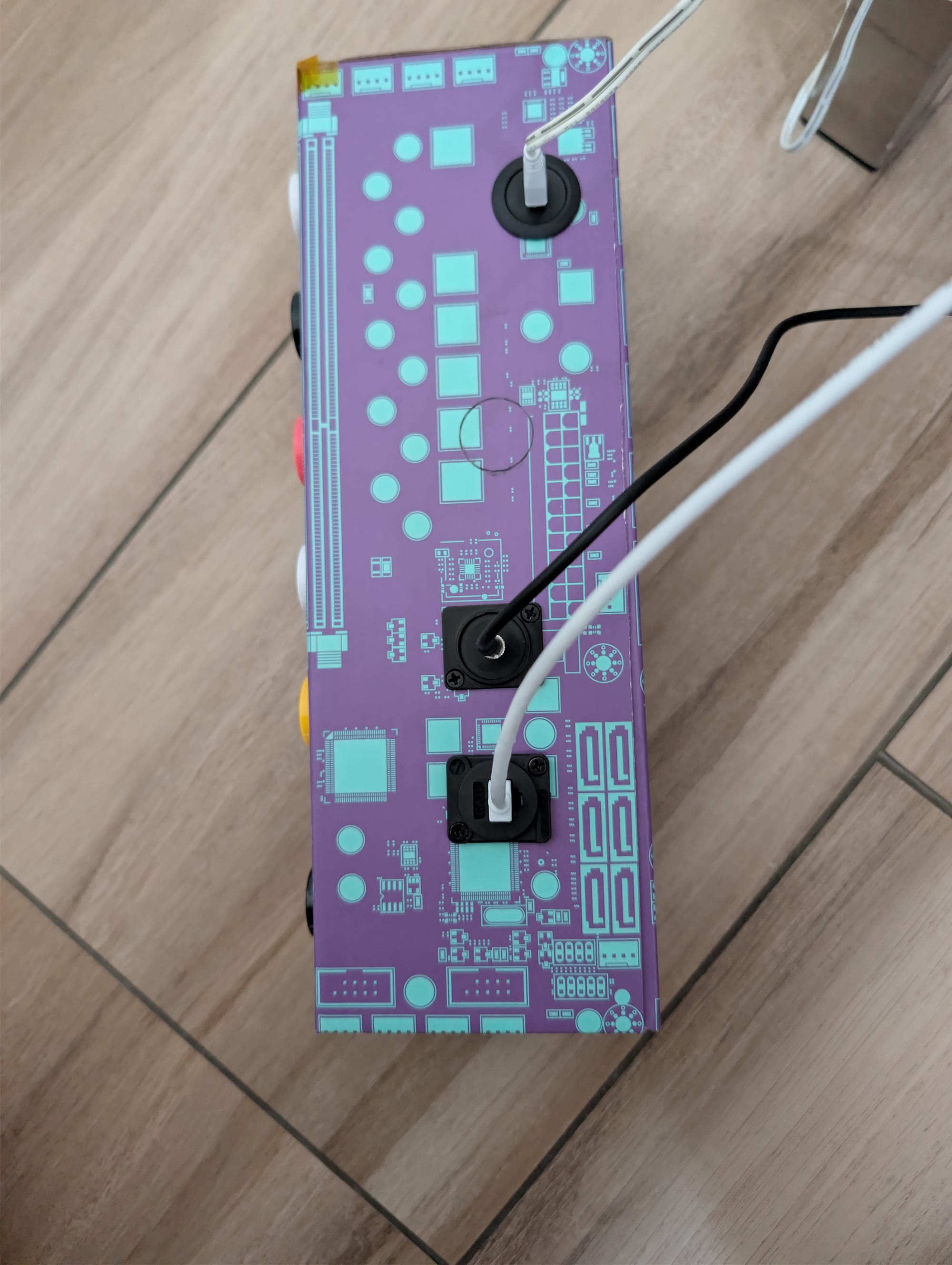
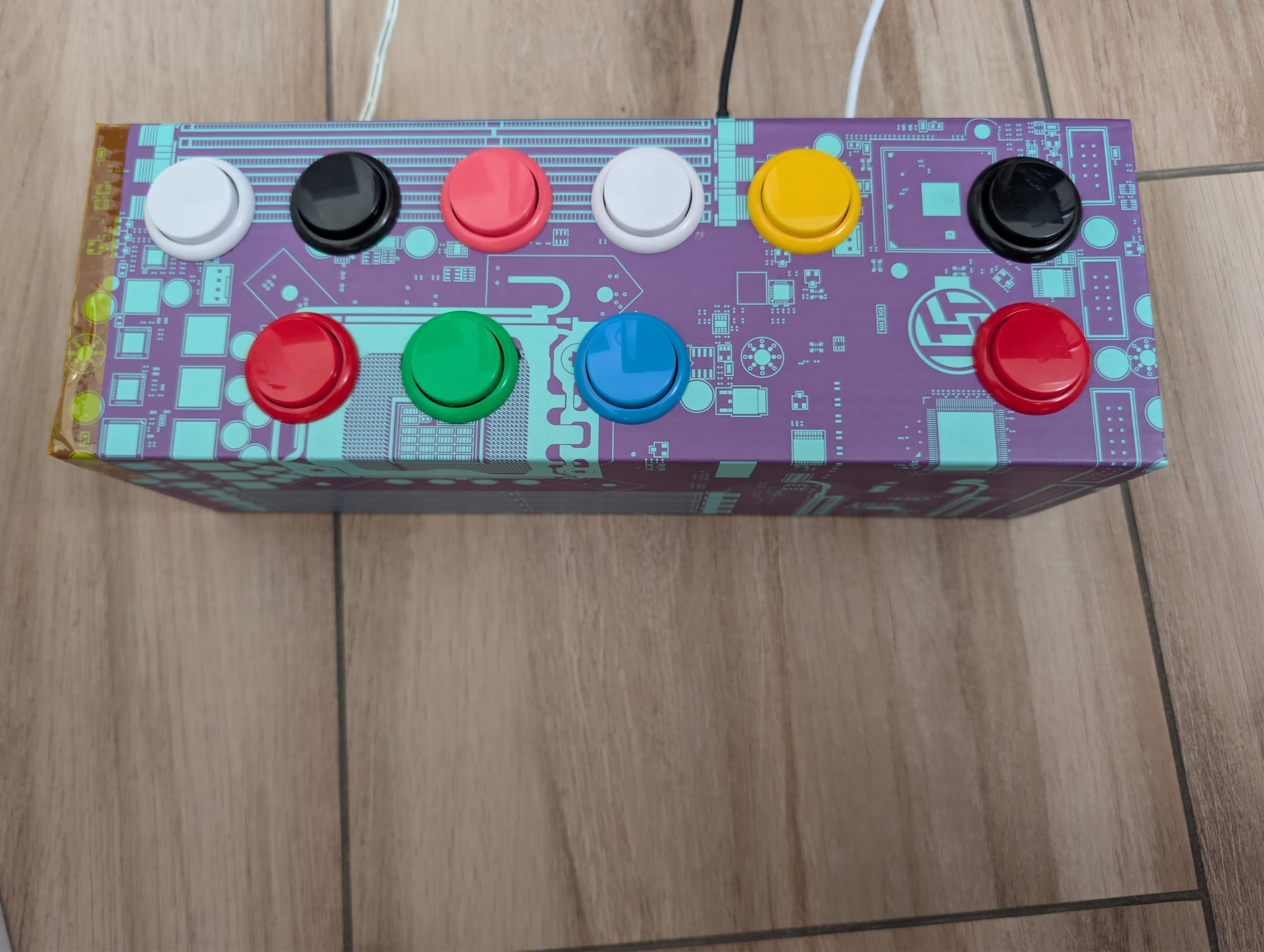
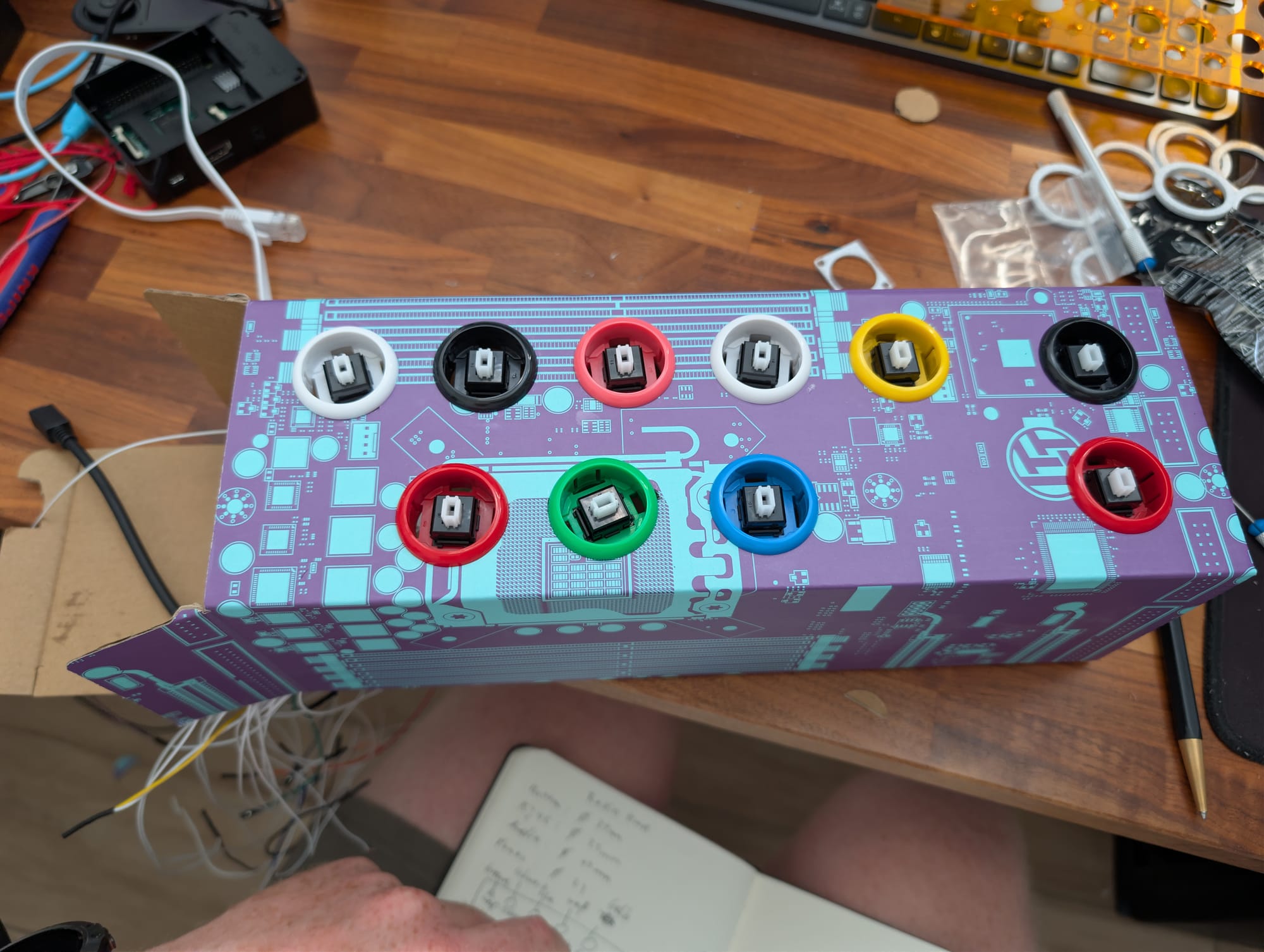
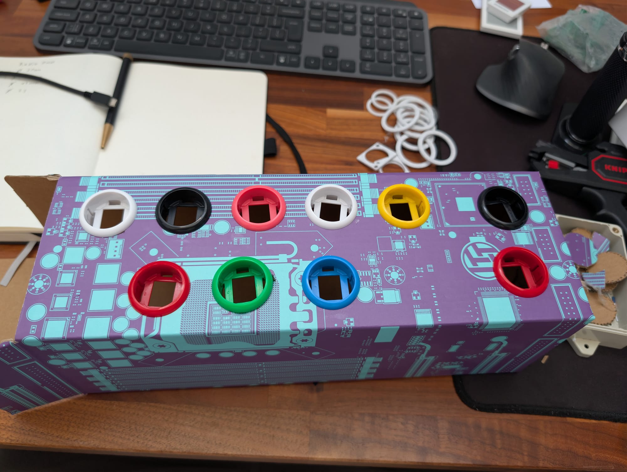
A few photos during the build process
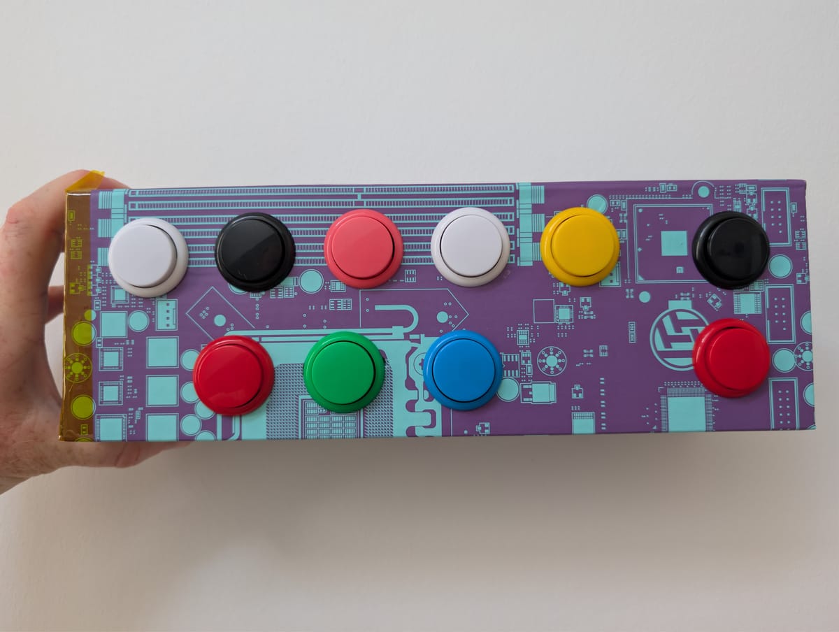
- Red and black on the side are for increasing and decreasing volume.
- 3 down below are for previous, play/pause, and next
- Previous and next does not work for radio, but you could add your own MP3s and playlists, and then it would work
- The 5 on top are preset for radio streams
Things I would do differently next time:
- Choose a box that can be opened on the top. Putting that rat's nest of wires back into the cardboard box was tough, and I was scared to break things. But it worked.
This was a quick and dirty project, and that was the goal. Get something running quickly. No overthinking, just building and getting it done.
That was fun!
Now it needs to survive shipping.
That is it for now.
I wish you a pleasant rest of your day! ☀️