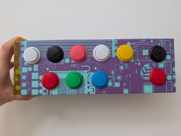
pc-switch version v1.1
Here I show you how I added proper labels to my pc-switch PCB.

On the weekend I had some time for a small revision regarding the pc-switch. One complaint I had myself: There were no labels on the board for the pins and therefore I myself did not know how to hook this up. 😅
So off I go to the next EasyEDA adventure.
Version Management in EasyEDA
First I wanted to create a new version or revision of my PCB. Turn out EasyEDA has that build-in. Just right-click and you see it right there.
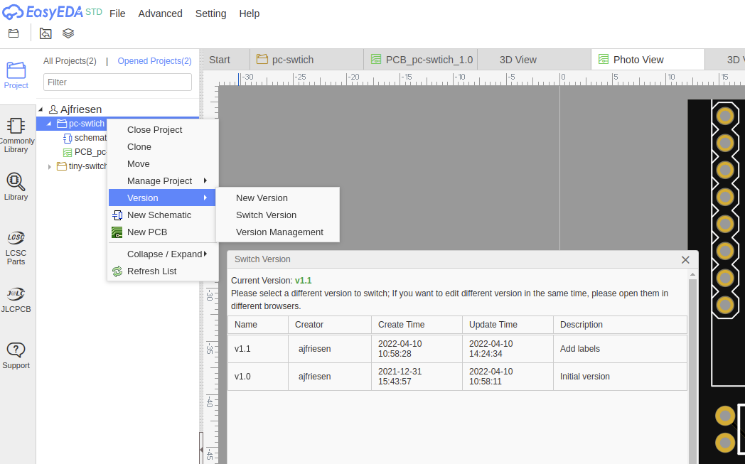
You can give each version your own name, pick it and change it as you like. Easier than I expected.
Adding proper labels
This one was a little trickier I must say. I might not have found the best solution, but I have found an easy one that worked for me. Take that like everything else with a grain of salt.
I first thought it must be done in the schematics but now, looks like this is done in the PCB section.
Removing labels from schematics views
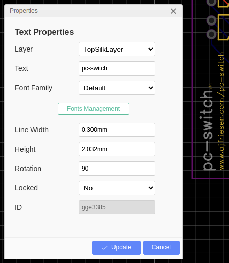
First I had to hide the "labels" which were automatically created by the PCB conversion. For that, you just click on the text of that component and move it from the TopSilkLayer to the Document layer.
After doing so you will not see them in the 2D or 3D rendered version. You can even hide the Document layer to have less of a mess on the screen.
Adding labels
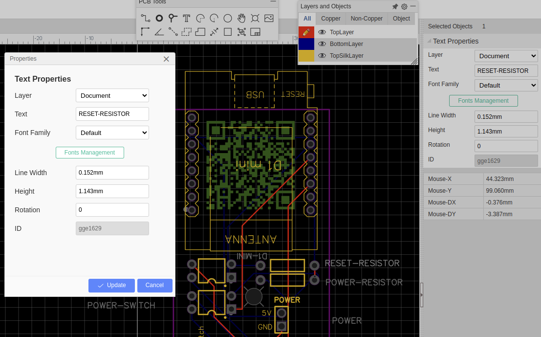
Second I wanted to add the real labels and not the technical-looking ones from the schematics. For that, I just used the Text object from the PCB Toolbar. After adding your text you can right-click and adjust all the properties.
After playing around with the properties, moving around some components and new redoing the auto-routing I was satisfied.
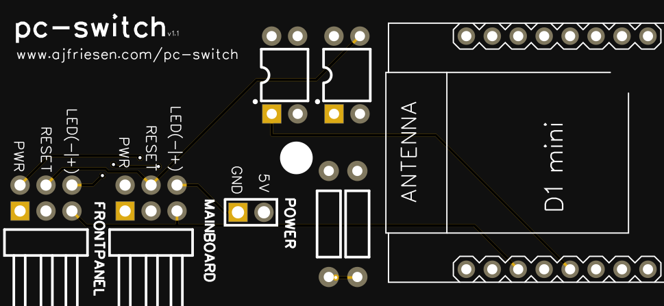
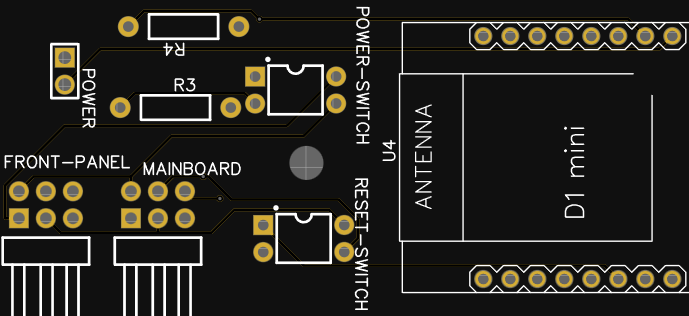
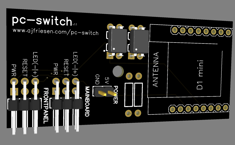
pc-swtich (left side with labels) (right side my first PCB prototype version)
Adding a QR Code
I wanted to have a QR Code on the PCB as well. First I tried out a random QR Code generator from the internet and placed that image on the PCB TopSilkLayer.
Then I tried to test the QR Code with my phone the cheap man's way. Holding up my PCB against the screen, zoom out until it is roughly the size of the real one and try to scan that thing!🤓
Then I realized that my QR Code was way too small. Like 5 mm and that scanning did not work.
Then I decided to put the QR on the back. When researching I stumbled across this awesome QR Code extension for EasyEDA:
 turbobabr
You do not need a random website anymore and the biggest pro is: You can create the QR Code as big and small as you like with quality! Most sites will just give you a small png and if you need to scale it up you might get problems with quality.
Installing is damn easy and shown in a GIF on the repo. Just download the zip, extract files to a folder, add that files to your EasyEDA Extensions and done.
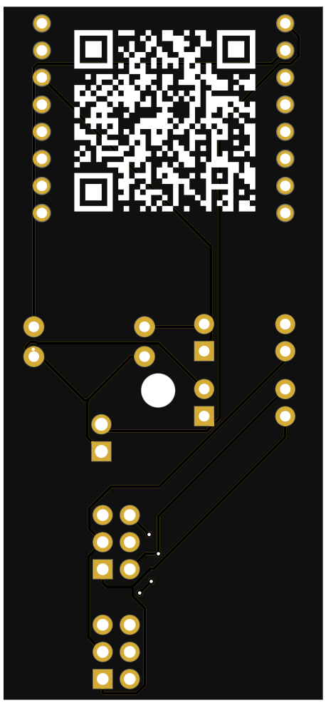
Create the QR Code with the newly added menu item QRCODE and place the QR Code wherever you want. I wanted to place the QR Code on the back because that is the only way I had space left 😜. Same approach as before. Choose your QR Code object, change the Layer to BottomSilkLayer, and you are done:
That is it for now. Now I just need to order a new batch and add the updated Gerber files to the pc-switch project site. Members of this blog can download everything and build their own pc-switch.