First PCB version for the pc-switch for ESPHome - My first PCB design ever
I have built a PCB and have documented my process as an absolute beginner in this field. The pc-switch can control your pc power switch, reset switch via Home Assistant and ESPHome.

As you may know, I was working on the pc-switch some time ago. My first DIY hardware. I have documented the process from the prototype stage to a working PCB in this blog post.
Enjoy! Maybe?
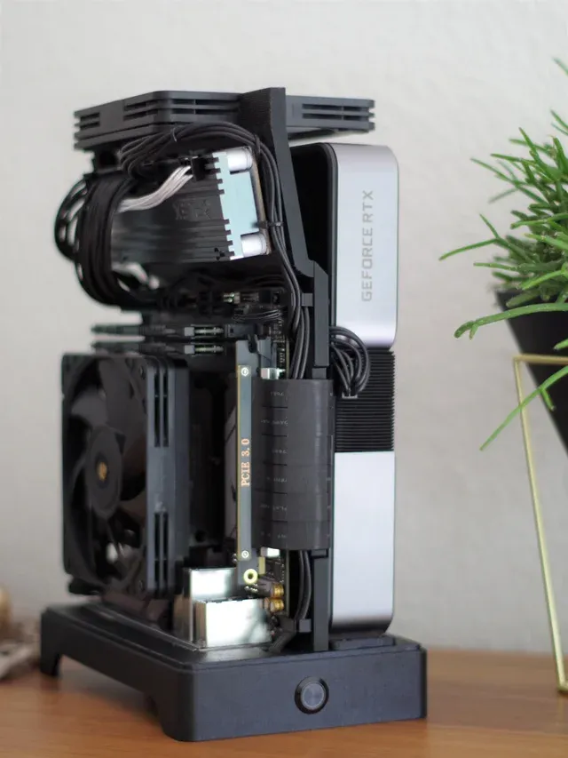
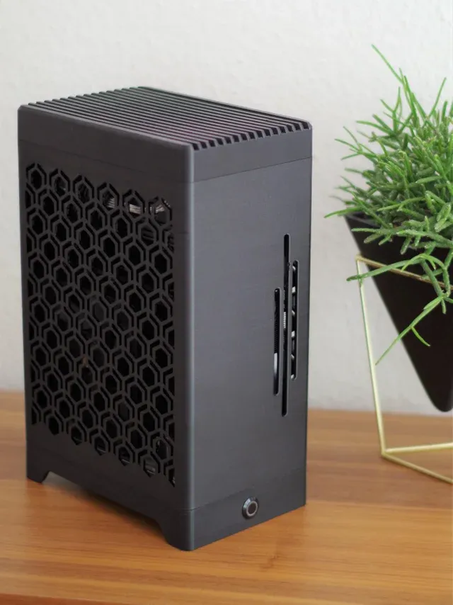
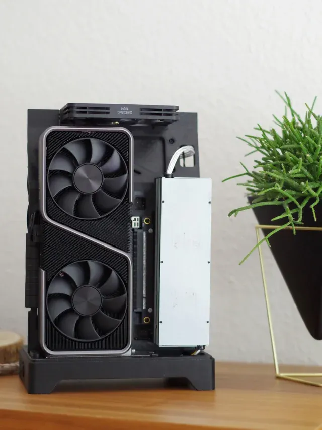
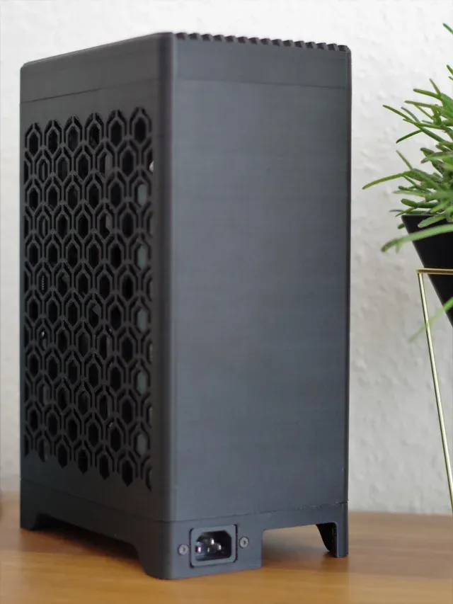
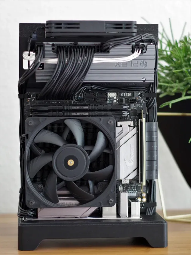
A friend of mine has built this sick 3D printed SFF (small form factor) case. It is called Project häx. It is pretty cool. Check out the Reddit post if you want more info on the 3D printing part. Here are some pictures:
He wanted to power on and off the PC via Home Assistant. That is where I offered to help him to build something. As you may or may not remember, I was building the pc-switch prototype some time ago actually for this project.
So time went by and a few weeks ago I sat down with a friend and designed my first PCB. That thing is tiny after all and so I needed him for the measurements, where and how to mount the PCB, and thinking about the thickness as well.
Designing the PCB
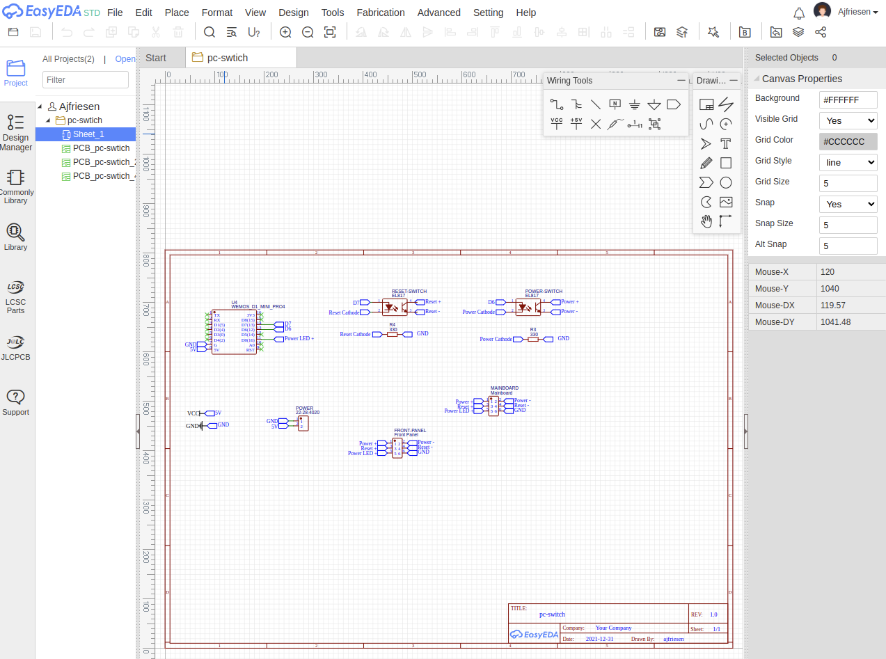
So I fired up the EasyEDA online editor. Why, you ask? Another friend already designed a few things in there and I wanted to be able to ask him if I needed help and no software install. Just a browser that is all you need.
So I mapped out all the components in the schematics view. Man, it was frustrating to find parts. I am not familiar with the technical terms for angled pin headers, resistors, and what Wemos D1 mini shall I use? There are hundreds of them out there and the part library is sometimes confusing. But hey that is part of the learning process I guess. After some time I figured it out and had the simple schematic ready.
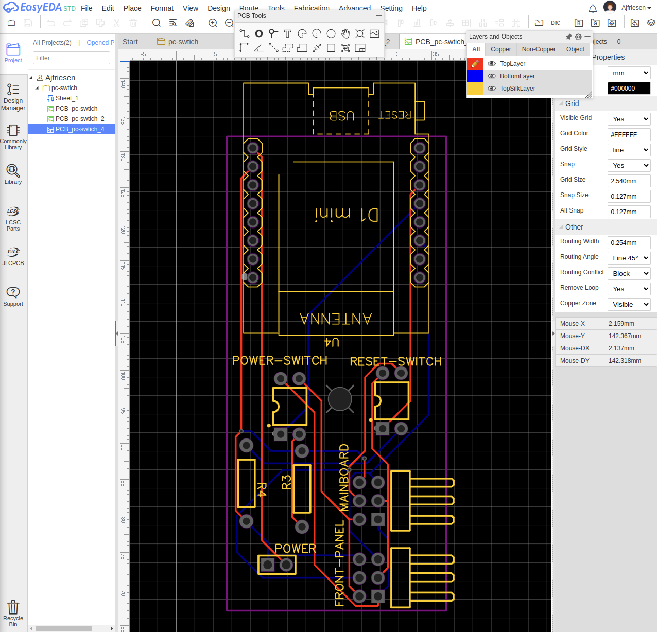
Next, I had to figure out how to create a board from the schematic. You need to "Convert Schematic to PCB". There you can decide about the size of the PCB. After this process, you have to pick your components and place them somewhere on the board.
Now we just miss the copper lanes. The wiring so to speak. You need to use the Route Tab and pick autoroute. I highly encourage you to install the local autoroute tool. Sometimes the cloud version just did not go through which is fine. You just need to download a file and run it as an executable binary. This worked on my Linux Desktop and will also work on Windows and Mac OS.
After many attempts of trial and error, I got the PCB. You can also have a preview in 3D! Pretty cool!
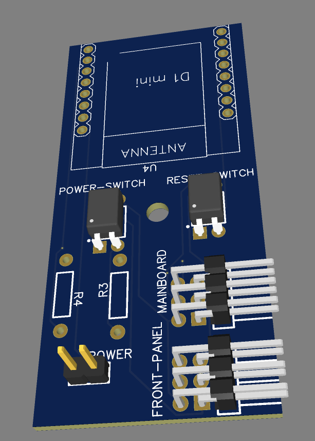
This was not just a straight process going from the schematic to the cringy 3D model. It was Google, YouTube, try and error all over sthe place over several sessions. I had to train a little before I actually sat down with my friend and figure out the measurements, pin placement, etc. Learning as you go and enjoy the frustration.

Ordering the PCB
So now we have supposably a PCB design. Where and how do I order one?
I remember JLCPCB from some YouTube videos and just took that one. I guess marketing does work well, does it? 😅
Also, I remembered that you need to change some settings depending on where you get PCBs. These can be changed in EasyEDA as well. These setting depend on the manufactures capabilities to create tracks with a certain width and via diameters.
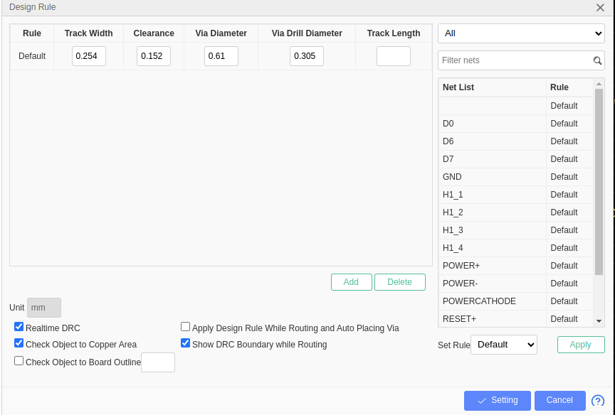
So we searched the internet and found random tables which recommend different design rules. We just picked one we felt good with. No engineering there, more or less random. I also do not remember the website with that information otherwise you would see a link now. 🤣
Next up we see the order form from JLCPCB. We had to create the Gerber file. Whatever that is, but heck we just found the button in EasyADA and uploaded those files.
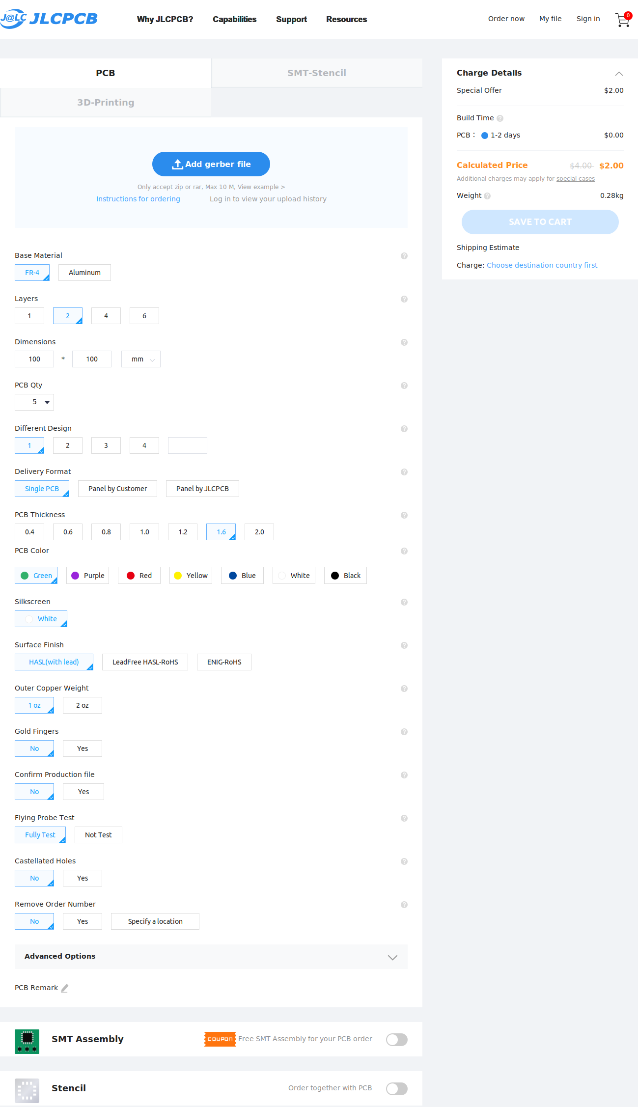
As you can see in the form, it is now just picking and choosing some options. The most important option you need to be very careful about is... obviously... the color. Just kidding there is just one color, BLACK!
And after paying we just had to wait.
Assembly and testing
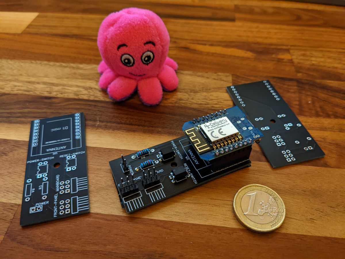
Don't they look beautiful? At least for the first PCB design, it looks good to me (the absolute beginner 🤓).
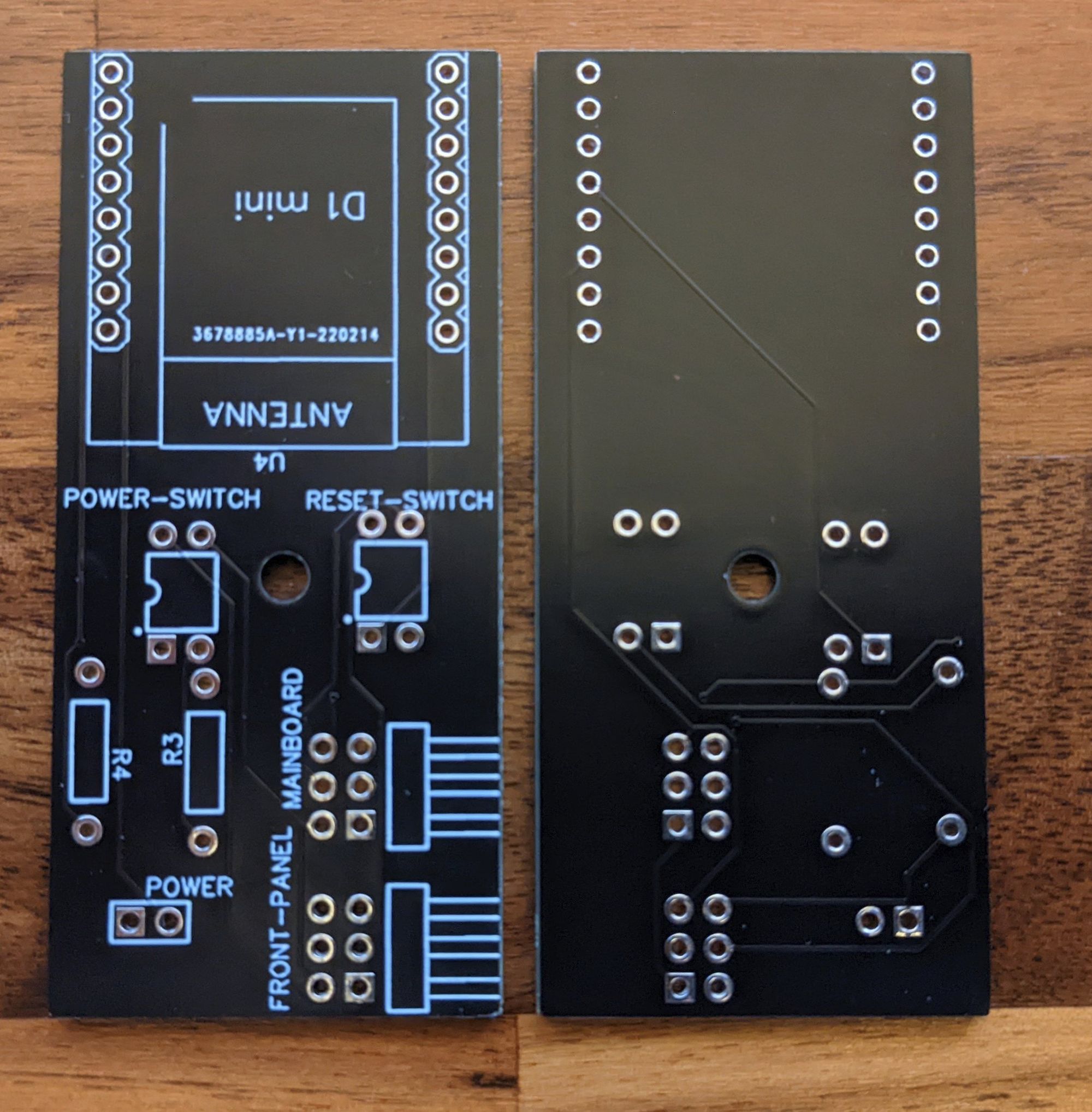
I mean nothing is aligned but hey, prototyping. Perfect won't get me to a finished state.
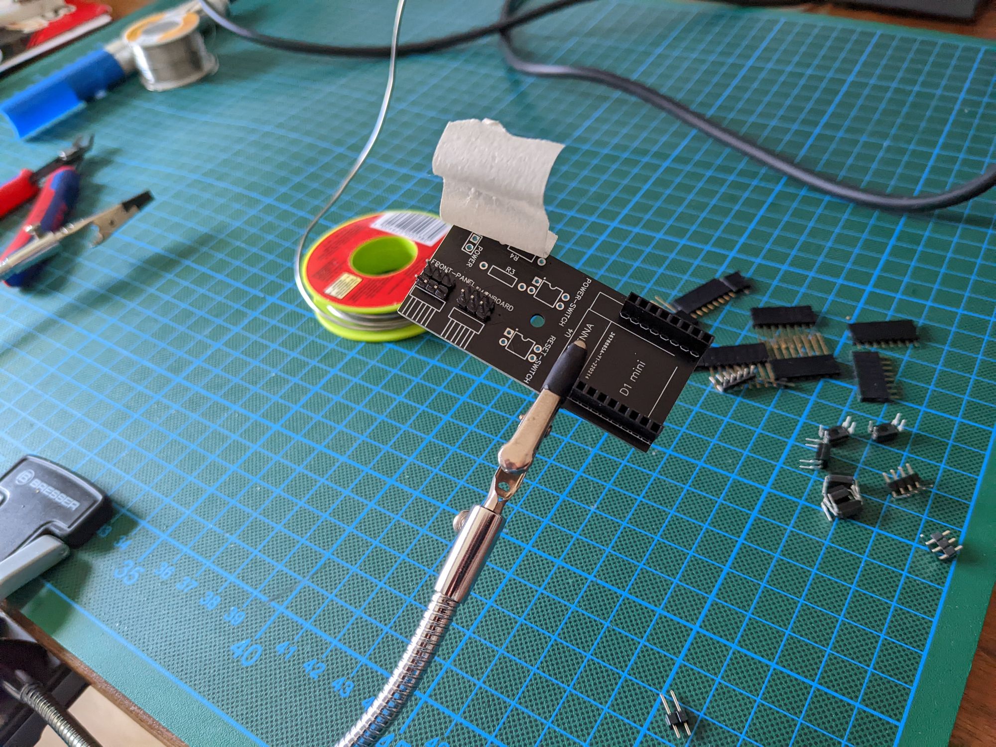
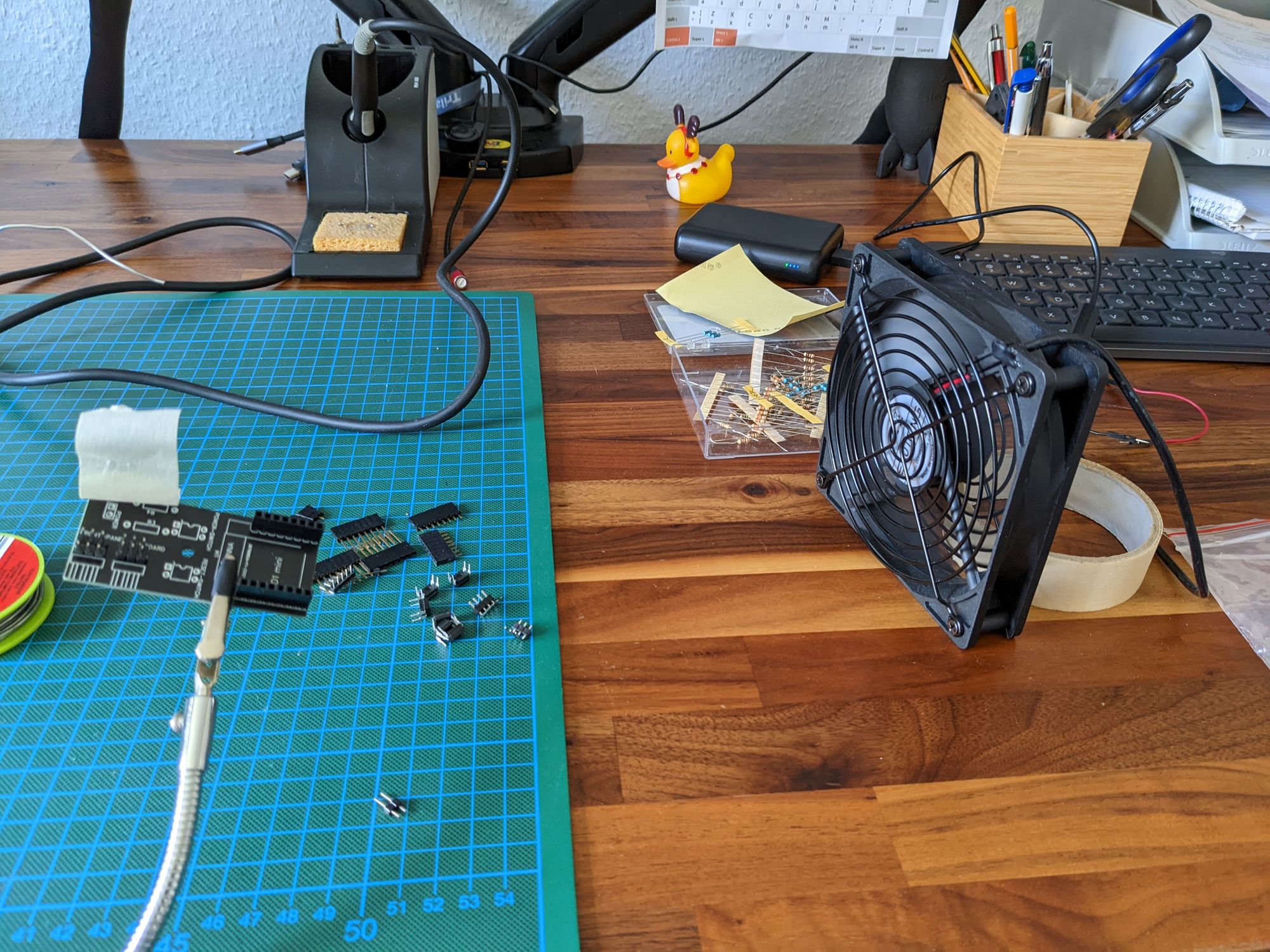
Off we go. Getting out my soldering iron and stuff. Always a pain, because it is the same desk I do my day job (remote only), work on my projects, play games, etc. Have to clean it up after every use. So let's get this done, shall we?
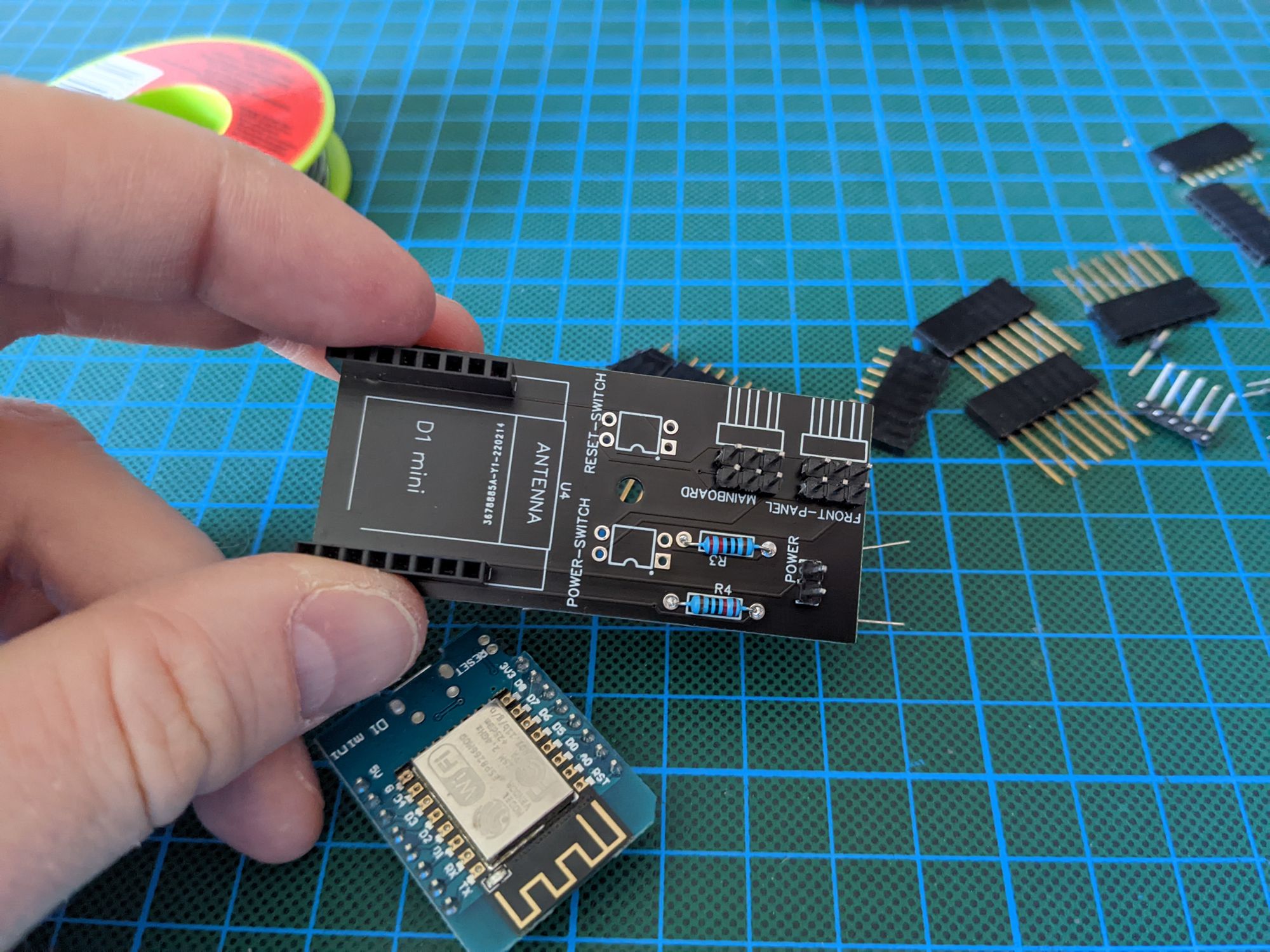
The only problem I had was remembering what pin is doing what. There were labels for the front panel pins and the motherboard pins, but which was for the power switch, reset switch, and power led? And where are plus and minus? Had to look it up in the schematics again since my brain did not memorize the decisions made then. Thanks to the simplicity of the PCB this was not too annoying. When doing this again and in a more complex project I will definitely label things appropriately!
Integration testing with Home Assistant and the ESPHome firmware
Testing did not start to good. I did plug everything in and I could not flash my Wemos D1 mini. Turns out that gut was smoke. Not sure what happened but dead is dead.
The next Wemos D1 mini was easy to flash. Puh, I was thinking I had a flaw in my design/thinking. 💦
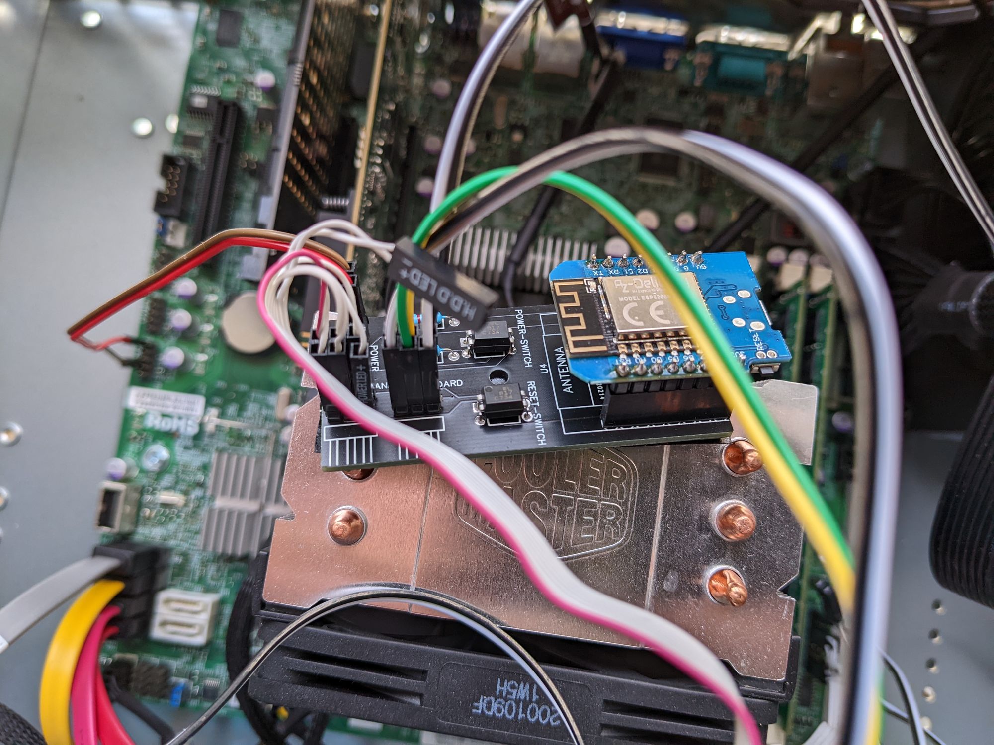
The second board worked almost fine in the beginning. Had to check and change the polarity for the power led pins and then everything just worked fine.
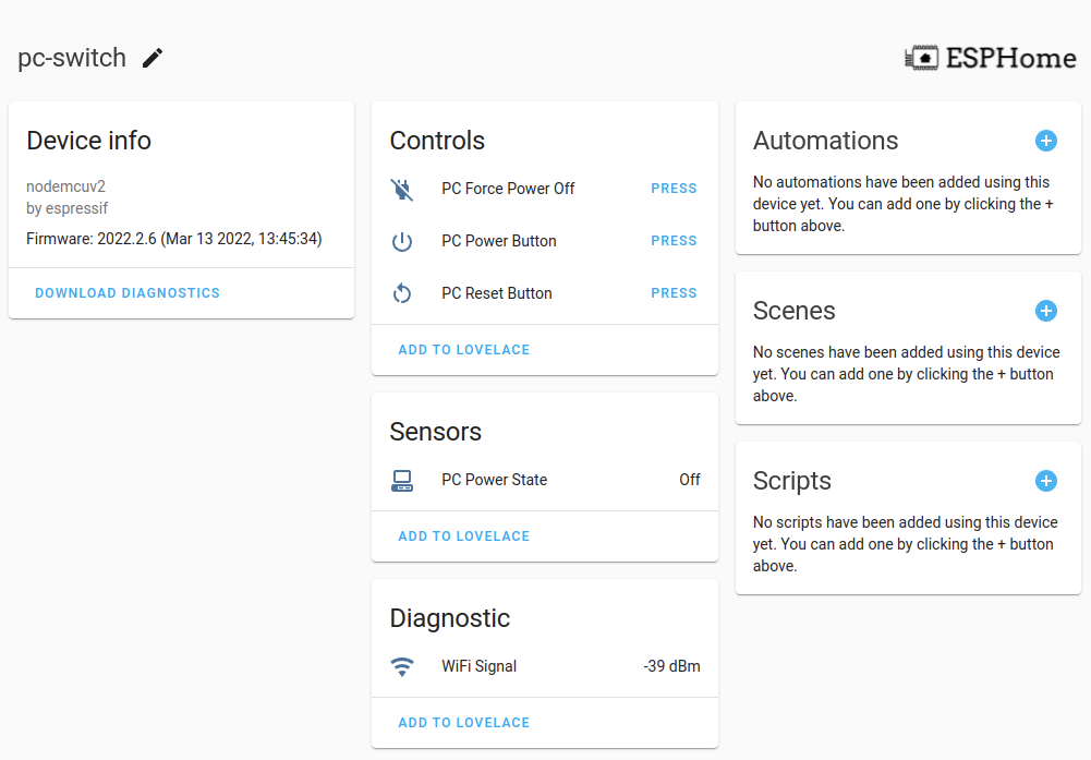
Here you can see what the pc-switch can do in the Home Assistant web interface or app:
Conclusion
I must say: It took some time but I think it turned out pretty well. And it was honestly not super easy but doable. I think doable is the most important part here, otherwise, I just might have flipped the table and aborted the project.
The project got some attention on Reddit and a few people even reached out to me via Email to buy this. I have no idea if it even makes sense to sell such a niche device and to figure out the legal obligation which you have as a manufacturer.
Maybe in the future, if people are really interested I might figure out a way to sell this.
But I will create a project page for the pc-switch. I will put down all the information needed to rebuild this by yourself. Members of this blog can just download the Gerber file and order their own PCB on whatever platform they like. The admittedly simple schematics will also be provided if you want to build your own form factor for example.
Here is the project page:

Do you want to build your own version? Please tell me in the comments below!
Are you interested in such a device? Let me know as well.
Maybe we can figure out how to bring this to people who really do not want to solder if enough traction is there.
BTW: I do not enjoy soldering, it is just necessary 😁